Каталог Покупателям Юрлицам Сервис Личный кабинет
0 0 0
Код товара: 1901655

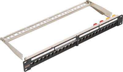
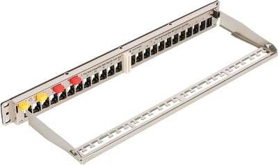
Коммутационная панель NIKOMAX для системы мониторинга Ver.2, 19", 1U, наборная, под 24 модуля типа Keystone серии LS, UTP/STP, с заземлением, с органайзером, черная NMC-RP24-LS2-1U-MT

Код товара: 1901655
Коммутационная панель NIKOMAX для системы мониторинга Ver.2, 19 Коммутационная панель NIKOMAX для системы мониторинга Ver.2, 19
17 320 ₽
Привезём 12 ноября
Новосибирск другой город

Покупаете на юрлицо?

Цены указаны с НДС 22%. Заказывая на сайте, выберите оплату Счёт для юрлиц. Бесплатная доставка по Новосибирску, ЭДО.

Участвуем в конкурсах и помогаем их готовить. Подбираем решения.

Для особых условий обращайтесь в наш b2b-отдел.

b2b@119.ru   +7 (383) 373-26-19

Похожие товары
Сортировка
Фильтры Сбросить

Коммутационная панель NIKOMAX для системы мониторинга Ver.2, 19", 1U, наборная, под 24 модуля типа Keystone серии LS, UTP/STP, с заземлением, с органайзером, черная и похожие 3 из 3

Фильтры
Сортировка
Нет товаров, соответствующих выбранным фильтрам

Сбросить фильтры

Характеристики
Характеристики
Connection style
Shielded
Temperature ranges
Storage from -40 to +70 ° C. Operation from -10 to +60 ° C
Warranty
1 year
Number of ports
24
Height, U
1 (44.5 mm)
Marking
All ports are numbered, there are additional marking areas
Installation
Cabinet or 19 " Rack
Color
The front panel is black, the body is metallic (nickel)
Housing material
Nickel-plated steel, 1.5 mm
Type of installed modules
"LS" series keystone modules (modified "FT")
Depth in rack (with organizer), mm
160
Packaging
Individual - cardboard box
LED Color
Blue
Описание
Patch panel is designed for installation of cables in different SCS subsystems and connecting separate network components to one another using patch cords. The LED monitoring system is a new solution from NIKOMAX that simplfy the administration of Structured Cabling System. The monitoring system allows: Construct a table of connections and easily change it if necessary; Highlight active / inactive ports to simplify administration of the system; Track all changes in real-time in the system; Log all changes in the system. The monitoring system is based on a special design of patch panels. Each port of the LED panel is equipped with a special contact that defines the physical connection. This design solution allows the use of standard four-pair RJ45-RJ45 cables. In the new version of the monitoring system, the USB connection is no longer used, the panels support full remote control over the network, including through the web interface. You can download a database from AutoCAD. NIKOMAX LED monitoring system has several advantages: Remote network management, including through the Web-interface; Importing a database from Auto-CAD; Simple, flexible and universal modular design. It is not necessary to replace the entire panel, if something fails. LED modules, Keystone modules, controller modules - can be easily replaced; The use of standard patch cords for switching ports, which is extremely convenient for the further operation of the system; The system is built on NIKOMAX «LS» modules (modified «FT» modules), which allows: Combine the different types of modules on the panels in any required configurations; Easy and quick to change configuration; Modules are available in shielded and unshielded versions, categories 5e, 6 and 6A; Use the NMC-FT-TOOL tool for quick termination, which allows simple and convenient installation, saves time. There is no need to replace the panel if it failed, broken LED blocks, Keystone modules, controller modules can be replaced individually; The system is able to cover a project of any scale; Cost effective. Software Installation and operation manual and software are provided with the monitoring system. You can control the system through software installed on a PC, and through a web interface. Basic Elements and Principle of Operation Each panel is equipped with a special controller module that collects and transmits information about the connected ports. Controllers are divided into two types: Master (red) and Slave (yellow). Master controllers are equipped with RJ45 ports to control the system via a network connection. Master controllers are installed on each first panel in each separate cabinet. The connection of patch panels in the rack occurs in series, with separate cables, through the yellow connectors located on the back side. On all “Slave” patch panels, yellow Slave controllers are installed, which collect and transmit information to the first panel. Up to 19 slave panels are connected in series to a patch panel with a master controller; that is, up to 20 panels with a monitoring system of connections can stand in one rack. Each Master controller is equipped with a LAN port for connecting to a switch on the network using a standard RJ45-RJ45 cable. Thus, all panels are connected to the racks in the network, and its own network address makes each rack a separate independent unit, allowing you to bypass the serial connections between them.Remote control over a local network allows you to cover a building monitoring system of any scale. The system administrator can connect to the network via Wi-Fi or a wired connection, so he will receive all relevant information on the status of all connections and can manage the system without getting up from his workplace. For example, you can specify a series of ports between which you need to re-switch. At the site, in the server room, the administrator will not need to search for the necessary information in the cable log: the ports required for switching will already be highlighted. Power Supply Each LED panel has a 5V / 3A power connector, which must be connected to a common electrical power outlet. To do this, the package includes a special connecting cable 1 to 17 connectors, one side of which is connected to the power adapter and the other to the panels. Depending on the mode of operation of the backlight, the power consumption of the system can vary significantly. Nevertheless, the system is very economical. Data are presented in the table below: Channel Model For the monitoring system to work, it is required to create channels according to the cross-connection model. The need for duplication is related to the principle of system operation: to register changes, channel switching should be between two LED panels, one of which is connected to permanent cable lines leading to outlets at workplaces, and the other ports are switch ports. Thus, the cable infrastructure is divided into two groups: “workplace subsystem” and “active equipment subsystem”, each of which is assigned its own LED panel. Based on the design features of the patch panels, they use specially modified Keystone modules with the “LS” index in the article number. The basis for the modification was the components of the NIKOMAX Fast Termination series, so the “LS” modules are compatible with the NMC-FT-TOOL quick termination tool and are available of all the same types as the “FT” modules. You can connect to the active equipment with the help of pass-through connecting Keystone modules. The modules have an RJ45 / 8P8C connector on each side and serve to connect two patch cords with the appropriate connectors. “LS” series modular pass-through modules are modified specifically for use with the monitoring system.